Download File
Please provide your contact information below to proceed with the download. We only use this to enhance your experience and offer relevant updates.

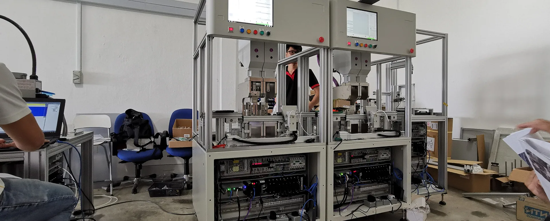
In modern manufacturing, checking only the final dimensions of an assembled component may not be enough to confirm that the process was completed correctly. A part can meet a final dimensional requirement while still having an underlying assembly problem.
Force Displacement Monitoring provides a way to monitor what happens during the pressing or assembly process itself. Manufacturers can evaluate the complete relationship between force and displacement throughout a machine cycle by measuring pressing force and tool or ram movement at the same time.
This makes Force Displacement Monitoring particularly useful for press-fit, insertion, forming, staking and other controlled assembly operations where changes in force and movement can reveal process abnormalities.
Force Displacement Monitoring is an in-process quality monitoring method that measures force and displacement simultaneously during a pressing cycle.
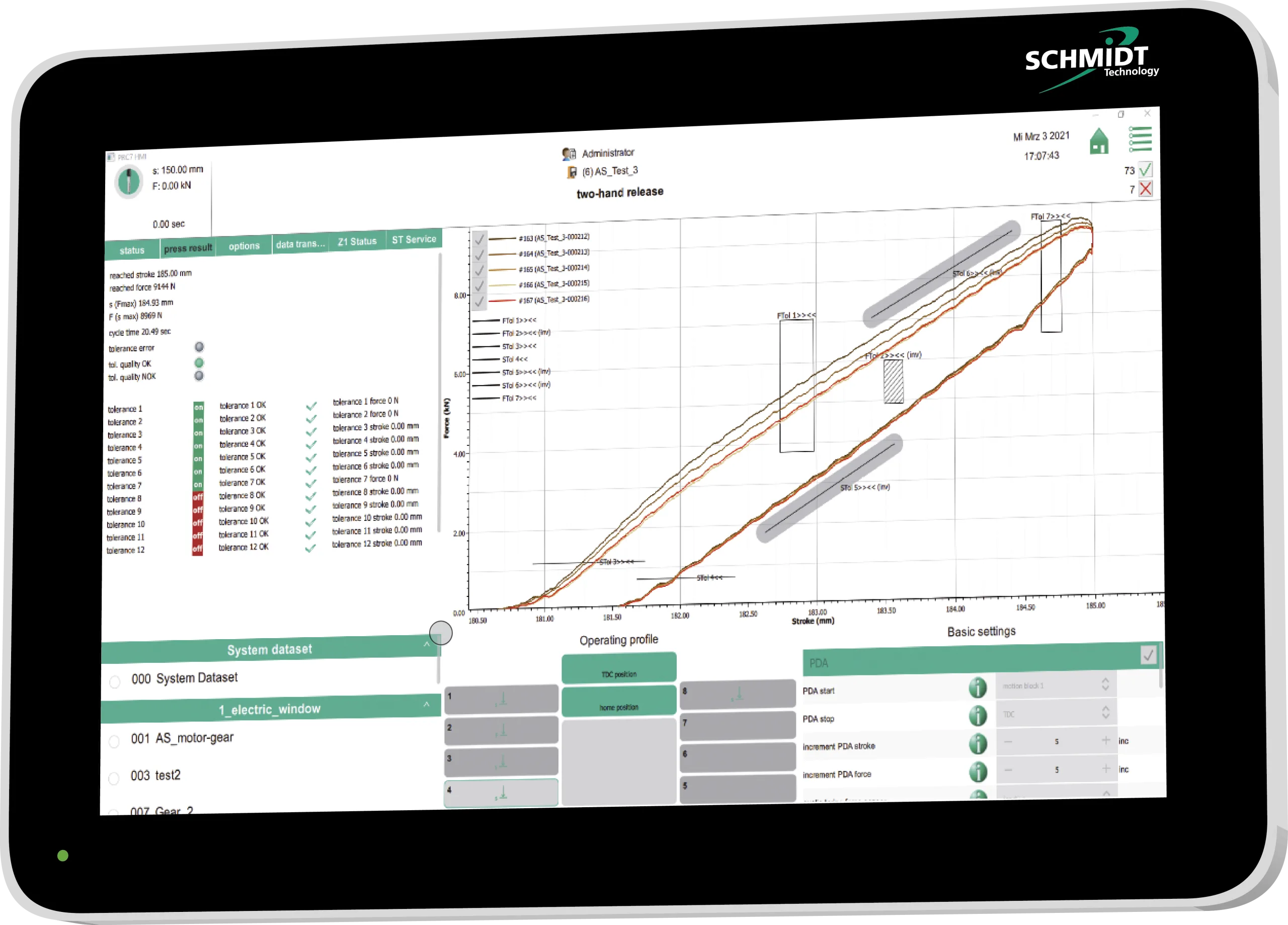
A force sensor measures how much force is being applied, while a displacement or position measuring system records how far the press ram or tool has moved. The controller synchronizes these signals and creates a force displacement curve.
The curve can then be compared with predefined acceptance criteria or tolerance windows to determine whether the process is within the required conditions.
Instead of asking only, “Did the component reach the final position?”, manufacturers can examine how the component reached that position.
This distinction is important because abnormal resistance, unexpected movement or changes in the force pattern can indicate an assembly problem before the finished product leaves the production process.
Because each force measurement is associated with a corresponding tool position, manufacturers can see how force changes as the component moves through the assembly operation.
This provides considerably more process information than monitoring peak force alone.
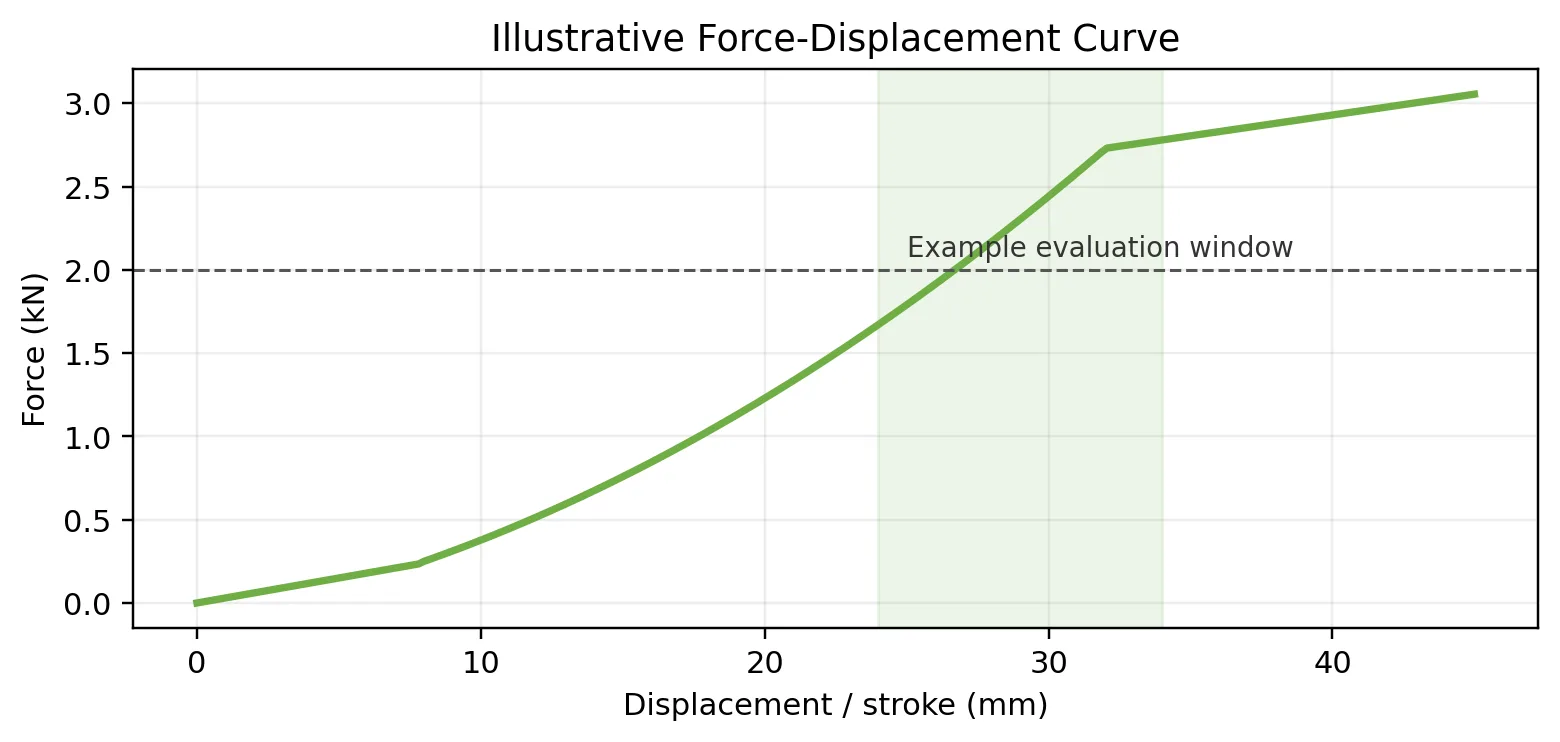
A force-displacement curve represents the relationship between the force applied to a component and the displacement of the pressing tool.
For a typical press-fit or insertion operation, the curve may begin with relatively low force while the tool approaches the component. Once contact occurs, force begins to increase. As insertion continues, interference and friction can cause further increases before the component reaches its intended final position.
The exact curve depends on the part, material, tooling and assembly process. Therefore, there is no single curve shape that can be considered “normal” for every application.
Manufacturers may look for changes such as:
This allows the monitoring system to evaluate important stages of the assembly rather than relying on one measurement.
The exact monitoring capabilities depend on the press and controller, but typical variables include:
| Variable | What It Helps Verify |
| Force | Whether the required pressing force is achieved |
| Displacement/stroke | Whether the required movement or position is reached |
| Peak force | Maximum force during the cycle |
| Minimum force | Whether force remains above a required level |
| Force at a defined position | Changes in resistance during a specific stage |
| Position at a defined force | Changes in fit, geometry or material behaviour |
| Tolerance window | Whether the curve follows an acceptable process path |
| Overall curve behaviour | Whether the complete assembly signature is consistent |
Depending on the controller, time, cycle duration or speed-related values may also be available. Using several criteria together can provide a more reliable assessment of the assembly process than using a single peak-force value.
The controller compares the measured cycle with programmed acceptance criteria.
For example, an application may require the force to remain within an upper and lower limit while the component moves through a particular displacement range. The system can also check whether the curve enters, passes through or exits a predefined tolerance window correctly.
Depending on the controller, other evaluation methods can include:
The appropriate evaluation method depends on the application and the controller’s capabilities.
Force Displacement Monitoring can identify many assembly defects when those defects create a measurable change in the force/stroke signature. However, detection capability should always be validated against the actual component and production process.
| Potential Defect | How Force Displacement Monitoring Can Detect It |
| Incorrect insertion | Commonly detectable through abnormal force/stroke progression |
| Missing component | Commonly detectable when expected contact or force rise is absent. |
| Misalignment | Often produces an early or excessive force rise |
| Excessive friction | Typically appears as higher force over part of the stroke. |
| Cracking | Cracking may produce a sudden force drop or another abnormal curve event in some applications. Detection should be validated for the specific process. |
| Wrong component | Detectable when the wrong component produces a sufficiently different force/stroke signature. |
| Incorrect final assembly | Often detectable if the sequence or final seating differs from normal |
One of the main advantages is that the system evaluates the assembly process itself, rather than relying solely on a final dimension or a single force reading.
This provides several potential benefits.
Every press cycle can be evaluated against defined criteria, allowing manufacturers to monitor production continuously rather than relying only on sampling.
Changes in the force displacement signature can reveal abnormalities during assembly. This can help identify process variation before larger quantities of defective products are produced.
Where appropriate, monitoring can reduce reliance on destructive inspection and manual checking by providing an automated assessment of every monitored cycle.
The force displacement curve provides process information that can help engineers investigate why an assembly operation is producing abnormal results.
Recorded process data can help manufacturers understand how tooling, components and process parameters affect assembly performance.
Where the system supports data storage, process curves and OK/NOK results can be retained for production traceability and later analysis.
Force Displacement Monitoring is not limited to one type of press. It can be applied to pressing or assembly equipment capable of providing reliable force and position signals.
Examples include:
The monitoring system typically works alongside the press, sensors, controller, machine control or PLC interface, HMI/software and, where required, data-storage or MES connectivity.
The technology can be applied across different industries. In practice, the type of assembly process is often more important than the industry itself.
It can be useful for applications in:
The system is particularly useful when changes in force and displacement can indicate whether an assembly or production step has been completed correctly.
Common applications include:
Therefore, when evaluating whether Force Displacement Monitoring is suitable, manufacturers should focus on the characteristics of the process, such as whether force and position change predictably during the operation and whether process variations can be identified through the force displacement curve.
| Consideration | What to Consider |
| Sensor Selection | The force sensor range and resolution should be appropriate for the application to ensure accurate measurements. |
| Machine Rigidity | The tooling and machine frame should be sufficiently rigid to provide reliable and repeatable measurements. |
| Part Loading | Components should be positioned and loaded consistently to maintain stable force displacement results. |
| Tool Alignment | Proper alignment between the press, tooling and component is important for repeatable monitoring results. |
| Acceptance Limits | Limits should be established using validated good and known-defect samples rather than arbitrary values. |
| Calibration | Sensors and the monitoring system should be periodically checked and calibrated as required. |
| Tooling Wear | Tool condition should be controlled because wear can gradually change the force displacement signature. |
Electric press systems are particularly suitable for applications requiring controlled force and stroke measurement.
For SCHMIDT® ElectricPress systems, such as the EP343, as an example where force and stroke are measured directly within the press system. With PRC control and the appropriate software options, production criteria can be evaluated and process data or curves can be stored or transferred.
This type of integrated approach can help manufacturers combine controlled pressing with in-process quality monitoring within the same production station.
Force Displacement Monitoring provides manufacturers with a more detailed view of what happens during a pressing or assembly cycle. By synchronizing force and displacement measurements, the system creates a process signature that can be evaluated against validated acceptance criteria.
Its value is particularly relevant where assembly quality depends not only on reaching a final position, but also on how the component moves and responds to force throughout the process.
For manufacturers handling press-fit, insertion, forming, staking, spring seating or similar applications, Force-Displacement Monitoring can provide a practical foundation for 100% in-process quality control, process troubleshooting and production traceability.
The most effective implementation starts with a stable mechanical process, suitable sensors, properly aligned tooling and acceptance criteria established from actual good and known-defect samples.
Want to see how Force-Displacement Monitoring can fit into your pressing or assembly process? Explore our solution to learn how integrated force and displacement monitoring can support in-process quality control, process visibility, and traceability.
View our press solution or contact our team to arrange a demo and discuss your specific application.
It measures pressing force and tool displacement simultaneously during an assembly cycle to evaluate how a part is being assembled. This ensures total process quality rather than simply checking if a component reached its final target position.
Sensors measure force and ram position continuously from the start of the stroke, while the controller pairs both signals on a shared time base. The system generates a visual curve, evaluates it against preset limits, and outputs an immediate OK or NOK process result.
It catches missing components, component misalignment, wrong parts, excessive friction, cracking, and incomplete seating. These defects reveal themselves whenever an abnormal assembly condition alters the expected force signature.
It integrates with electric, servo, hydro-pneumatic, pneumatic, and manual presses, as well as custom assembly stations. Common applications include press-fitting bearings, inserting connectors, staking, riveting, and verifying spring compression.
Manufacturers must ensure machine rigidity, precise tool alignment, correct sensor sizing, and consistent part loading to maintain process stability. Acceptance limits should then be set using verified good and defective production samples, accompanied by routine sensor calibration.
